
Have you, like me, ever wondered what lives inside your expensive black or chrome boxes with the Hasselblad logo on it?
Well, you obviously don't want to go and wreck your expensive equipment. And looking at the technical drawings in the repair manuals is a bit of an abstract exercise at best.
So, when I got my hands on an affordable 500C/M body I decided to take a sneak peak inside.
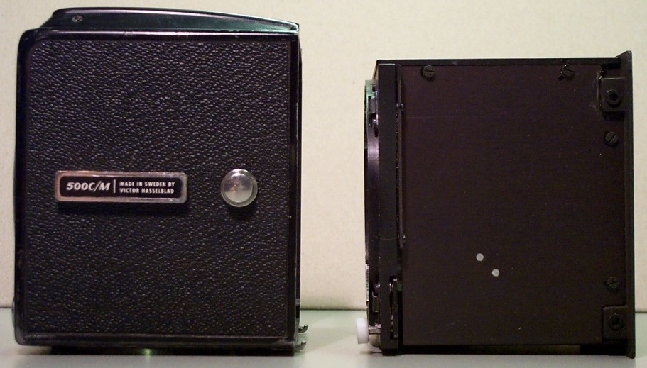
It helps to know that the shell of the body fits like a kind of jacket around the actual optical box. The dimensions and alignment of that box determine the sharpness etc of the images. The jacket itself does not. So DO NOT loosen any screws from the box unless you have the training and the alignment tools etc to properly align it again!
You can slide the shell off after removing the film back, the viewfinder, and focusing screen. The tripod coupling screws are what keeps the shell in place, so the coupling needs to be taken off.
The transport knob now needs to come off. Then the single retaining center screw needs to be removed. Once done, you see this
The right side of the camera is where the interesting parts are. There is a really intricate set of gears, levers, springs etc that work in close concert to make your camera cycle through its exposure cycle. Just marvel at this mechanical masterpiece, don't fool around with it.

In contrast, the left side is truly boring
Viewed from the front, note the round white (Teflon) bushing. This is what releases the bajonet when the lens release button is pressed. Don't forget to put it back on its center pin when you perform the reassembly.

Seen from the back with the jacket shifted off the camera box.

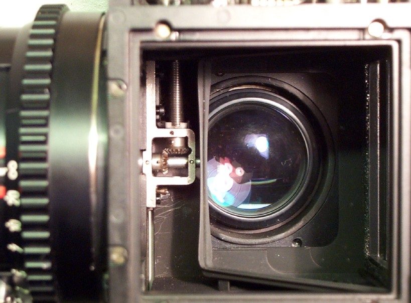
Now for a look into one of the more (in)famous parts of a Hasselblad: the shutter drive mechanism. The shutter drive mechanism is covered by a truly thin metal cover. Once removed you can see shaft that cocks and releases the shutter.
The drive gear is connected to the one that has the little screw (as seen from the back of the camera). This screw you can use to cock the lens if it is inadvertently released. Remember you cannot remove the lens unless the shutter is cocked. You can just see the end of that screw in the center of the mirror.
The PME prism has a plastic cover, which can be taken off after removing a bunch of screws located underneat the vinyl covering.

Note the photo sensor just above the eye piece location. This explains that keeping your eye close to the rubber eyepiece is essential to avoid stray light entering the sensor and causing false measurements.

On the frontside you find the battery compartment.

On the left hand side are the dials for the film speed and maximum lens aperture.

The right side holds all the electronics. Note the adjustable resistors. Stay away from these, as they are used to calibrate the meter. Sofar I have not seen docs thay explain how to do that so...

Recently I got my hands on a reasonable priced 500EL/M (thanks Ulrik!). Having gotten the taste of it, and finding justification in the fact that the EL/M had a problem with the upper 'lid' of the auxiliary shutter not opening properly, I decided to take a look inside the EL/M.
Note that I had the Hasselblad service docs available, I strongly recommend against trying any of this work without the proper docs. The EL/M is quite a bit more complicated than the 500C/M. Getting it together again with the proper gear timing is quite complicated!
In addition to that it is equipped with a quite strong drive motor, which according to well-informed sources is quite capable of wrecking gears, lenses etc. Be careful out there..
The 500EL/M in its original chrome glory:


Before you start work on the camera make sure it is cocked and then remove the battery, the shutter release button and the glass fuse (it will fall out anyway at some point).
To get access to the 500EL/M's insides you first have to remove the right-hand cover of the motor unit. It is kept in place by only 2 screws, so this one is easy. Once you have removed the cover you get to see

Your entry into the actual 500EL/M body shell is via a small lid under the mode selector switch on the right hand side of the camera. The lid is kept in place by a single screw in the bottom right which hides under the leatherette. Taking the lid off shows you

Actually, in the picture above I already removed the small gear which connects the motor unit with the actual camera. Note the old grease everywhere.
Next step is to remove the actual motor unit from the casing. There are 4 screws holding it in place. Once removed you will find yourself with

A closeup shot of the motor unit.

You are looking at the 2 connector springs that connect to the batteries. Not shown is the fuse holder & fuse. It tends to fall out of the motor unit, and you will most likely forget to install it during re-assembly at least once (I did..).
Once the motor unit is taken out of the battery/motor housing you can now proceed to separate the motor housing from the camera shell. There are 4 screws connecting them together. To get access to them you need first remove the tripod plate. Of the 4 screws 2 are located below a folding-flap of the leatherette.

Once you have completed removing all the screws you will end up with 2 major assemblies, the motor unit housing and the actual camera as show below. Note the 4 holes for the screws in the motor unit housing.

Next step is the separation of the body shell from the actual camera. In order to do so you need to take the mode selector switch off the camera. Please note there is a spring hiding behind the knob.. Remove the round piece of leatherette from the selector knob, then remove the 2 screws now visible. The whole selector switch assembly can now be removed.


With quite a bit of figgling & dexterity you can now carefully slide the body shell off the mirror box. Take care of the gears, the body shell is quite a tight fit. Once you succeeded you are finally at the actual drive gears. Note that in the picture below the biggest gear has been taken off the mirror box already. As you can see a lot of old dirty grease throughout. All of this old grease I of course removed before re-assembly. Also note the spring around the selector knob assembly.

I also took the small gear off located on the right-bottom hand side of the mirror box. This proves to be an interesting one to get installed again as it determines the timing of quite a bit of the camera's internals. This it does together with the really small gear just above it. This operation is definitely not for the faint of heart.
Getting the upper lid of the auxiliary shutter operating properly again proved to be quite an easy job, it boils down to gently forcing it while holding the shaft it is mounted on with a pair of pliers. Knowing that you can only do this with the shell off the camera explains why a simple procedure like this is still an expensive one. Just getting that shell off takes considerable time given that you need to do all the steps outlined before you get access.
Getting it all together again is an entertaining job. Especially as you cannot mount the motor unit on the camera for testing without the body shell in place. The shell also acts as a spacer. I ended up creating a spacer from a piece of scrap aluminium plate so that I could observe all the gears. Not much to see with the body shell in place for obvious reasons..
While I had the camera apart I took the opportunity to change it into black trim


Thanks to Paul for trading the nice black 'jacket' for my chrome unit. He likes his cameras in chrome, I prefer mine in black, so we are now both happy.
Comments? Corrections? Please send them to Wilko Bulte.
All text & photographs are ©2005-2007 Wilko Bulte, the Netherlands.